Concentric Vent Kits


CONCENTRIC VENT KITS
  • Concentric vent termination kit for water heater.

  • These vents save time and money by reducing the amount of work required.

  • For horizontal or vertical venting, requires only one hole to be cut rather than two and easy assembly.

  • Includes all fittings will need to install the vent.

  • Please consult manual to your appliance prior to purchasing this concentric vent kit to ensure that it is compatible with your system and do not use the concentric vent kit for anything.

The concentric design cuts off the incoming fresh air and exhausts smoke. The preferred vertical roof terminal is not easily damaged, reduces the chance of absorbing pollutants, and sees less steam.

New Feature - A 4" vent screen is attached for new 4" Concentric Vent Kit as a accessory. The vent screen is designed to keep birds and leaves from drop into the exhausting pipe. Comply with UL 1738 standard.

Cut only one hole instead of traditionally cutting two holes through roof or side wall for exhaust and intake pipes to complete installation.

Typical Roof Installation

Determining the Location

Locate the concentric vent/air termination using the following guidelines:

  1. Ensure the total length of piping for vent or air remains within specified limits.

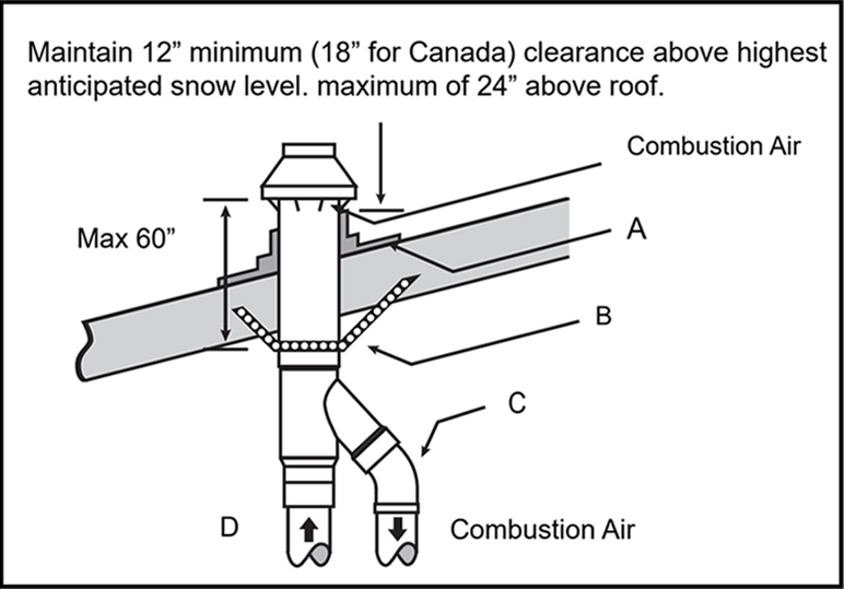
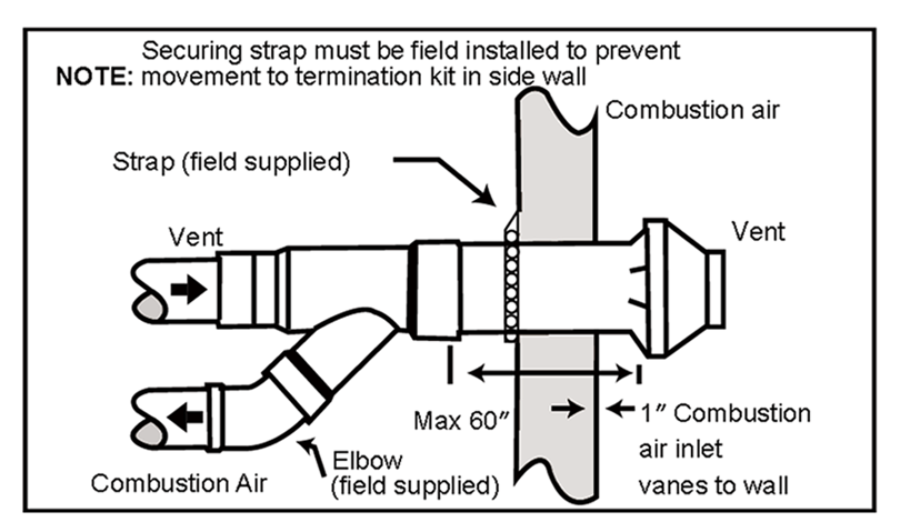
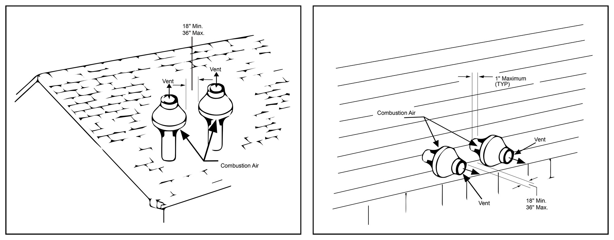
  2. Terminate the concentric vent/air assembly as illustrated in Figure 1.

  3. Ensure that vent and air piping connections comply with the instructions in this supplement.

  4. Take the surroundings into consideration when positioning the vent and air terminations:

    • Ensure that the termination is situated in a location where vent vapors will not harm nearby shrubs, plants, or air conditioning equipment, and where objectionable odors will not be produced.

    • Take into account that flue products will generate a noticeable plume as they condense in cold air. Therefore, avoid areas where this plume could obstruct window views.

    • Be mindful of prevailing winds that may result in condensate freezing or the accumulation of water/ice on building surfaces or plants where flue products come into contact.

    • Prevent situations where accidental contact with flue products by people or pets is possible.

    • Avoid placing the termination in areas where wind eddies may affect performance or cause re-circulation. This includes avoiding locations inside building corners, near adjacent buildings or surfaces, window wells, stairwells, alcoves, courtyards, or other recessed areas.

  5. Maintain Clearances to Termination as Follows:

    • Keep at least 6 feet from adjacent walls.

    • Do not place closer than 5 feet below roof overhangs.

    • Ensure a minimum height of at least 7 feet above any public walkway.

    • Keep a distance of at least 3 feet above any forced air intake within 10 feet.

    • Maintain a minimum of 12 inches below or horizontally from any door or window or any other gravity air inlet.

    • Ensure that the termination is not susceptible to damage from foreign objects, such as stone or balls, or susceptible to the buildup of leaves or sediment.

    • Locate the vent outlet so that the air inlet terminates at least 12 inches above the roof or snow line, as depicted in Figure 1. (For Canada, the minimum distance is 18 inches.)

    • Do not terminate the vent closer than 4 feet horizontally from any electric meter, gas meter, regulator, relief valve, or other equipment. Never terminate above or below any of these within 4 feet horizontally.

    • Do not connect any other appliances to the vent pipe or multiple boilers to a common vent pipe.


Figure 1.


Prepare Roof Penetration

  • Create a 5-inch diameter hole to accommodate the 4½" termination outside diameter.

  • Insert a galvanized metal thimble into the vent pipe hole.

  • Adhere to all local codes for isolating the vent pipe when passing through floors, ceilings, and roofs.

  • Provide flashing and sealing boots sized for the concentric termination outside diameter of 4½ ".

  • Mount the termination as depicted in Figure 1, without making any alterations to any termination component.


Vent Termination Support

  • Do not modify any component of the concentric vent termination assembly.

  • Assemble and install all components as supplied.

  • Support the concentric vent termination at the roof penetration as shown in Figure 1.

  • The supports/bracing used must effectively support the termination assembly to prevent vertical slippage or sideways movement.

  • Ensure that the clamps used on the outside of the termination pipe do not cut into the pipe or have sharp edges that could cause cracks to form.


Sidewall Termination Details

  1. Determine the best location for termination kit.

    • Position the termination kit where vent vapors will not harm plants, shrubs, or air conditioning equipment.

    • Ensure that the termination kit is placed where it won't be affected by wind eddies or currents that might lead to the re-circulation of combustion products or the unwanted intake of airborne debris, leaves, or light snow.

    • Avoid locating the termination kit where it could be damaged by foreign objects, such as stones or balls.

    • Termination kit should not be positioned where it may be damaged by foreign objects such as stones, balls, etc.

    • Place the termination kit in a way that avoids objectionable vapors.

  2. Place the termination kit in a way that avoids objectionable vapors. 

  3. Assemble the concentric vent termination kit.

    • Cement Y concentric vent fitting to larger diam eter kit pipe.

    • Cement rain cap to smaller diameter kit pipe.

  4. Install the cemented Y concentric fitting and pipe assembly through the structure's hole. 

    Note: Ensure that no insulation or other materials accumulate inside the pipe assembly during installation.

  5. Secure the assembly to the structure as shown in Figure 2 using field-supplied metal strapping or equivalent support material. 

    Note: Ensure proper termination location clearance as depicted in Figure 2.

  6. Cement the field-supplied furnace combustion air and vent pipes to the concentric vent termination assembly.

  7. Run furnace through a complete heat cycle to ensure combustion air and vent pipes are properly connected to concentric vent termination connections.

Figure 2. Side Wall Installation

A minimum distance of 18" or a maximum distance of 36" must be maintained between vent terminations.


Multiventing Terminations

  • Never share venting or breach when two or more direct vent furnaces are located near each other; each furnace must have its individual venting.

  • A minimum distance of 18" or a maximum distance of 36" must be maintained between vent terminations.

1(4).jpg


Resources & Downloads

Type

Name